The transistor is the electronic version of a water valve or switch: A small change in the input setting causes a large change in the output. Actually a more accurate comparison would be a "fluidic amplifier". Basically, a transistor allows you to control a big current from a little current. How it does this is complex and more than you really need to know. If you must try to understand it, study diodes first or watch this video.
To use transistors, this is what you need to know: A small amount of current pushes the gate open and releases a larger current.
![]()
Transistors can be connected in different ways to form switches or different types of amplifiers.
When used as amplifiers, they work with resistors via Ohms Law to convert between current flow and voltages.
Common |
Base: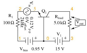 |
Emitter: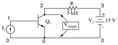 |
Collector: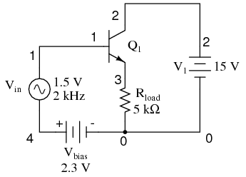 |
gain in |
voltage | power (both voltage and current) | i (current) |
stage |
alpha | beta | gamma |
input impedance |
low | medium | high |
output impedance |
high | medium | low |
| in | out | in |
This video does an excellent job of demonstrating the operation of a common emitter amplifier and it's use as a switch, and an inverter in digital logic.
Two transistors can be connected in series to form a digital logic NAND gate, from which all logic can be formed:
See also:
Russell McMahon [apptech at CLEAR.NET.NZ] says
- A transistor with opposite to normal voltage applied to C-E and base open will breakdown at some voltage - typically around 9 volts or so
- Adding a base to emitter resistor greatly reduces this voltage and softens the knee.
- Adding instead a collector - base resistor does similar but with somewhat less severity.
- IT MUST NOT BE ASSUMED THAT A REVERSE BIASED BIPOLAR TRANSISTOR WILL NOT CONDUCT THROUGH A REVERSE BIASED JUNCTION !!!!!!!!!!!!!
- Adding a series diode in series with the transistor's collector is a good idea when reverse biased C-E junction will occur if well defined operation is desired,
see PICList Thread %analog design challenge% for more.
FET: Difference between transisters and fets and why you might want a fet instead .Mark Willis says:
Transistors are current amplifiers, a FET is more like a voltage-controlled switch or (non-inductive) relay. I like HexFETs, just a quirk maybe. The logic gated ones have really been convenient in some packages I've made in the past. With a FET instead of a bipolar, you do have to make sure you saturate the FET (the logic gated FETs handle this for you.) The advantage is that, when switching a 1A 12V load (for example), instead of dissipating base drive * base current + Vce * Ice i.e (0.7V*(1A/hFE)) + (0.3V*1A) or about 0.31 watts in that transistor, you dissipate (1A^2*0R01) or 0.01W in that FET, if you're running off a battery pack that can make a big difference. (The 1A is the real killer, of course, in this case that was just the startup surge, and you need to saturate the transistor/FET for THAT; the sensor's supply current then dropped down to about 30mA - no use dissipating 20mA into that transistor, to keep a 30mA load switched on, the HexFET made a big difference here. Net savings, about 35% of the power budget, for one project.)
SCR: A Silicon-Controlled Rectifier, or SCR, is essentially a Shockley diode with an extra terminal added. This extra terminal is called the gate, and it is used to trigger the device into conduction (latch it) by the application of a small voltage. SCRs work like diodes except that they won't conduct until triggered, so there are 3 modes:
TRIAC: bi-directional SCR... current can flow through them in either direction and they can be triggered normally by either a positive or a negative current applied to its gate electrode.
4 quadrant TRIACS are in fact not equally sensitive in each quadrant. In Q4 (T2 -ve, gate +ve) the structure has to be adapted so that firing takes place via a multi stage process. This has secondary consequences of longer turn on than other quadrants - so needs longer applied gate current, and tolerates lower dI/dT so can lead to higher chance of hot spotting.
4Q TRIACs tend to false trigger and/or die more easily in reactive load applications. As a result special 3Q TRIACs were developed with a somewhat different internal structure that specifically prevents Q4 firing (a case of "less is more" :-) ). These are given a range of names by different manufacturers. I think "alternistor" is one such and Philips used the term "Hicom".This 1999 dated (quite possibly older) Philips app note provides an excellent overview of what is involved: "Three-quadrant triacs bring major benefits to OEMs" http://www.nxp.com/documents/application_note/AN_3Q_TRIACS.pdf
GTO: Gate turn-off thyristors (GTOs) are similar to TRIACs but provide more control by turning off when the gate signal is removed.
Archive:
See:
| file: /Techref/transistors.htm, 11KB, , updated: 2020/9/1 09:15, local time: 2025/10/19 22:49,
216.73.216.56,10-1-100-33:LOG IN
|
| ©2025 These pages are served without commercial sponsorship. (No popup ads, etc...).Bandwidth abuse increases hosting cost forcing sponsorship or shutdown. This server aggressively defends against automated copying for any reason including offline viewing, duplication, etc... Please respect this requirement and DO NOT RIP THIS SITE. Questions? <A HREF="http://www.ecomorder.com/techref/transistors.htm"> Transistors</A> |
| Did you find what you needed? |
Welcome to ecomorder.com! |
|
Ashley Roll has put together a really nice little unit here. Leave off the MAX232 and keep these handy for the few times you need true RS232! |
.