CHAPTER 4
We probably have all the tools needed already but let's make a small shopping list just in case.
- Small electrical type pointed nose pliers
- Small electrical type side cutters
- A soldering iron, say 40W
- A roll of solder with flux core (electrical solder not plumber's)
- Desolder wick
Now how to solder well, is a big topic. The gentleman below has said it all, far better than I could. If you are not sure and don't want to destroy our laboriously created PCB, or fry a transistor, then you should consult a web site like this one…
Basic Soldering & Desoldering Guide
by Alan Winstanley
http://www.epemag.wimborne.co.uk/solderfaq.htm
Fine, now we know all the precautions and things to do to make a good solder joint. One very practical detail is inserting the smaller components first. The reason is we insert from the top then we turn over the board to solder.
Now the components tend to slide out when not soldered. So you hold them in place with a fireproof finger. If the big components have already been soldered and the little one lies between them, then you can't get your finger to hold the small component. What should be a two second job can become very difficult .
Don't cut off the lead wires before soldering as bent slightly outwards they help to hold the component in place till we solder the leads. After cut them of as close as possible to the joins. This can avoid some nasty cuts if you accidentally slide your fingers across the underside of the board. Some of the cut leads are razor sharp, hence cut at low as possible. I once used to resolder after cutting to cover the lead edges but that is not a good idea as it reheats components.
Just a final word about the integrated circuits, especially the PIC. It must be mounted in a socket for an 18pin DIP as it will be removed to program and then reinserted many times before we are satisfied with the bike computer. Any special type of socket? No not really. I use a normal IC socket and it lasts a long time, indefinitely if you insert slowly pushing in alternately each end of the PIC.
For Taking the PIC out of the socket, I gently slide a small screwdriver blade between the PIC and its socket and lever up slightly , then I go to the other end and lever up slightly.
After a little with practice you can do this with no damage or strain to either the PIC or the IC socket..
Colour code
Resistor Colour Code
| Colours used band 1 and 2 |
Colour used as a number |
Colour as a decimal multiplier |
| BLACK |
0 |
X1 |
| BROWN |
1 |
X10 |
| RED |
2 |
X100 |
| ORANGE |
3 |
X1,000 or 1K |
| YELLOW |
4 |
X10,000 or 10K |
| GREEN |
5 |
X100,000 or 100K |
| BLUE |
6 |
X1,000,000 or 1M |
| VIOLET |
7 |
Silver / 100 |
| GRAY |
8 |
Gold /10 |
| WHITE |
9 |
Tolerances Gold= 5% Silver=10% None=20 |
Going back a little to before we insert the Fig 11 R47k components in the PCB. Do we need to learn the way components are marked, or maybe we already know. Here is a table with the basic information.
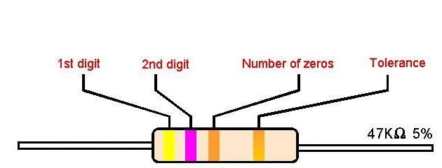
A 47kohm resistor is shown in fig11 as an example
Fig 11 resistor coding
Believe it or not we are almost ready to talk about the programming of the PIC
There are really so many programmers available for the PIC, that we couldn't possibly discuss the pros and the cons of them here. I would suggest we use a really simple cheap one, just in case we later need something better. But here cheap means reliable and one that does the job.
Any other condition? Yes, it has to be compatible with one of the types of board recognised by the ICPROG program we listed in chapter one as a FREE program.
Below we have a Picture of my own ( built from a kit) programmer. This is a com port model of the type called JDM ( I think JDM invented it). It uses the RS232 interface and has NO power supply. I t powers off the COM port output directly. As you can see from the photo, most of the components are diodes that either rectify the incoming signal or level shift signals.
The 9 pin D connector shows how small the whole thing is. The 18pin dip is empty but that is where we plug in the PIC for programming.
Just one word of warning. The socket has a V end and is mounted so that the V corresponds with the silk-screened white V. We MUST insert our PIC so that it's V or mark also corresponds and is at this end. If we put it in the other way round, it is probably ( not guaranteed) the end of the PIC. RIP…. = $$$$$
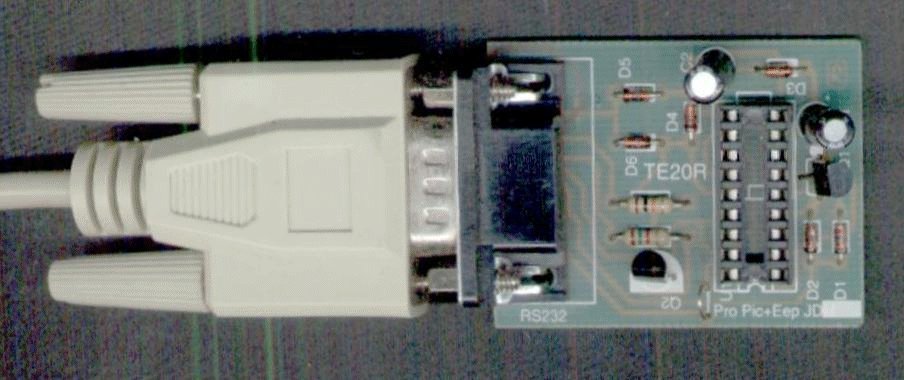
Fig 12 programmer for the pic 116F84A
Here we have come to the end of the steps to be able to program a PIC , not all PICs but quite a lot of them. Just to sum up we will reproduce the principal items from the various lists so that we can do a final check to see if there is anything we may have skipped.
| Item |
Source |
What it does |
| 16F84A data sheet |
Microchip Site and others |
Explains about the PIC |
| Text Editor |
EditPad Site |
For writing no-frills Text |
| MPLAB |
Microchip Site and others |
Test drive your code |
| PIC tutor |
Mikroelektronika |
Tells you How the PIC works |
| ICPROG |
Icprog site |
Stuffs the PIC |
| LCD data sheet 2x16 |
Hitachi 44780 controller |
displays speed, time dist. |
====+ Parts List for Bk3.dsn +====
C1,C7 2 100n
C2,C3,C8 3 1uF
C4,C5 2 22p
C6 1 3uF
D2 1 IN4148
D1 1 LED
R1 1 100k
R3,R4 2 1k
R5 1 2k7
R2 1 300k
R6 1 390
S1,S2,S3 3
U1 1 VOLTREG
X1 1 XTAL 4 MHz
Photographic list
- NaOH either crystals or as already dilute solution (0.7gm/ litre ) …1 litre
- FeCl3 100gr dissolve in 250ml
- Plastic dishes for the above
- Plastic bottles to store both after use… PLEASE LABEL what each bottle contains.
- Plastic stirrer for the Ferric Chloride solution
- A plastic funnel for poring each solution when making and after use into its own LABELLED bottle with a tight screw top ( children protection)
- POSITIVE Single-sided photosensitive copper clad board …the pcb we are making is 10 x 12.5 cm
- Test strip
- Exposure frame with cover glass. Any cheap photograph frame which press the glass hard against the back
- Tape
- Kitchen scissors
- Small electrical type pointed nose pliers
- Small electrical type side cutters
- A soldering iron, say 40W
- A roll of solder with flux core (electrical solder not plumber's)
-
DeSolder wick
And the last item was a.....
PIC Programmer
I must have forgotten something ..ah yes a Personal Computer
This
Chapter 4 is the end of the Hardware chapters the next section will deal with the programming of the PIC
16F84A


