Yes, I know I skipped September, it is still in the works but having digital camera issues. I can't seem to get good closeups. Yet. I will.
This issue is all about finding the distance from one point to another. Several methods are discussed:
 Laser
Laser
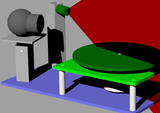
I've had the joy of working on a really interesting project with a real 3D CAD expert. Mostly I helped with some math and spewed out ideas, but the simplicity and the results are astounding. The project is a laser 3D scanner built for much less than any commercial unit.
The basic idea is probably best shown by these pictures from http://www.cyberg8t.com/pendragn/actlite.htm (which is no longer, but has been cached)
 |
- |  |
= |  |
And then the position of the laser line is used to calculate the depth of the object.
Because the Laser and Motor have to be timed and driven together both use the parallel port data lines. Only 3 of the 8 data lines are needed:
Also the software interface for the parallel port is easy to use with Jan Axelsons Inpout32.dll (available at www.lvr.com).
Routines are:
Laser True
Wait 0.3
ezVidCap1.SaveDIB ("c:\temp\laserOn.bmp")
Picture2.Picture = LoadPicture("c:\temp\laserOn.bmp")
Laser False
Wait 0.3
ezVidCap1.SaveDIB ("c:\temp\laserOff.bmp")
Picture1.Picture = LoadPicture("c:\temp\laserOff.bmp")
Step_Clock
|
This routine relies on the ezvidCap component from Ray Mercer
http://www.martin2k.co.uk/vb6/tips/x4.php
And a little easy port IO code:
Private Sub Step_Clock()
  Out Val("&H" + "0378"), 1:  Wait 0.1
  Out Val("&H" + "0378"), 0:  Wait 0.1
  End Sub

Private Sub Laser(switch As Boolean)
  If switch = False Then Out Val("&H" + "0378"), 0
  If switch = True Then Out Val("&H" + "0378"), 8
  End Sub
' Set the pixel color values.
For Y = 0 To Picture1.ScaleHeight - 1
  For X = 0 To Picture1.ScaleWidth - 1
    With pixels(X, Y)
      .rgbRed = Abs(CInt(.rgbRed) - pixels2(X, Y).rgbRed)
      .rgbGreen = Abs(CInt(.rgbGreen) - pixels2(X, Y).rgbGreen)
      .rgbBlue = Abs(CInt(.rgbBlue) - pixels2(X, Y).rgbBlue)
      If (.rgbRed > filter) And
       (.rgbGreen > filter) And
       (.rgbBlue > filter) Then
         .rgbRed = 0
         .rgbGreen = 0
         .rgbBlue = 0
      Else
         .rgbRed = 255
         .rgbGreen = 255
         .rgbBlue = 255
         End If
       End With
    Next X
  Next Y
|
This routine is adapted from the book Visual Basic(r) Graphics Programming: Hands-On Applications and Advanced Color Development, 2nd Edition by Rod Stephens for image processing and edge detection.
Angle = (Frame / LastFrame) * Pi * 2
For PicY = 0 To Picture5.ScaleHeight - 1
  Z = PicY
  For PicX = 0 To Picture5.ScaleWidth - 1
    R = (Picture5.ScaleWidth / 2) - PicX
    R = R / 0.5
    With pixels(PicX, PicY)
      RetR = .rgbRed
      If RetR = 0 Then
        X = R * Cos(Angle)
        Y = R * Sin(Angle)
        Print #1, X; ","; Y; ","; Z
        End If
      End With
    Next PicX
  Next PicY
|
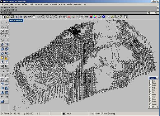 And the
result is a "point cloud" that describes your subject. Additional software
will be added to process the points into lines or faces, smooth and reduce
the complexity of the image.
And the
result is a "point cloud" that describes your subject. Additional software
will be added to process the points into lines or faces, smooth and reduce
the complexity of the image.
Now, this process can, and has to some degree, been done with a microcontroller. Here are the potential problems and how they are avoided:
 Sonar
Sonar
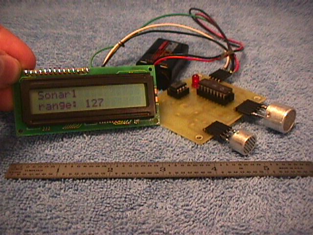
This simple sonar ranging device eliminates a lot of the usual discrete components by executing complex functions in the software of the microcontroller. Several times per second, the it generates a few cycles (about 8) of a 40 kHz square wave on an output that directly drives the transmitter element. It then begins counting "ticks" (fast program loops) which will accumulate until it either detects a response from the 567 tone decoder or a maximum period has expired. Immediately following the 40 kHz burst, the output of the 567 chip is ignored for a short time. This is because the 567 will detect the burst, and the transmitter element will continue to ring or resonate for a short time. The 567 tone decoder chip is a phase locked loop designed to detect when the input frequency is within a certain pass-band. The passband or detection range is determined by the values of the discrete components connected to it. This makes it very easy to use. The 567 has been around for many years, it's cheap, and very useful. Ultrasonic sound waves emitted from the transmitter element travel through the air, hit an object and bounce back to the unit where the receiver element detects them. The output of the receiver is amplified and sent into the 567 chip. The 567 chip drives its output low when it detects the reflected 40 kHz signal. It will react to all reflections so it may produce more than one output pulse, but this version of the code will only register the first one. Several readings per second are averaged and a value proportional to the detected distance is sent out via a serial line. The pictures show this connected to a serial LCD. Be aware that the value is for demonstration purposes only and not been scaled to any actual units of length like feet or centimeters. You would have to add your own code or lookup table to display specific units of measure.
The program is designed to run in different modes. The dip-switches are used to select the mode of operation, such as "normal pulse o/p", "continuous tone o/p" with is used for tuning the 567 for best detection, "binary serial o/p", "ascii serial o/p", etc.
The processor has a "serin" pin which can be used as a control input from another processor. Through this pin, it could receive instructions but this block of code is unfinished and should be tailored to your application. If selected, nothing will happen, however, it would be a simple matter to add code that would allow the input to act as a "logic enable" or to accept various serial commands. Alternatively, the serin pin could be programmed as some sort of o/p.
 The "serout"
pin is used to output the range test results. In ascii o/p mode, the results
are sent with the LCD-Backpack's value for the "I" instruction (#254) value
first that instructs a backpack-LCD or serial-LCD to enter "instruction mode".
The next byte sent is the address of line2 (#192) which sets the cursor of
the LCD to the start of line 2. Then three ascii digits are sent, MSD first,
center digit, LSD last. If the result is a BCD number less than 3 digits,
spaces are sent to clear those digits from the display. In binary o/p mode,
the straight binary test result is sent.
The "serout"
pin is used to output the range test results. In ascii o/p mode, the results
are sent with the LCD-Backpack's value for the "I" instruction (#254) value
first that instructs a backpack-LCD or serial-LCD to enter "instruction mode".
The next byte sent is the address of line2 (#192) which sets the cursor of
the LCD to the start of line 2. Then three ascii digits are sent, MSD first,
center digit, LSD last. If the result is a BCD number less than 3 digits,
spaces are sent to clear those digits from the display. In binary o/p mode,
the straight binary test result is sent.
The transmitter is a 40kHz transducer from Digikey, part# P9895-ND.
The receiver is a 40kHz transducer from Digikey, part# P9890-ND.
The PCB design uses several surface mount components. It saves a lot of hole drilling and lead bending and clipping. Also, assemblies end up smaller, better looking and easier to modify or service. Soldering surface mount (especially the larger variants) is ease
;Filename: SONAR1.SRC
;Created: MAY.4.97
;Last Modified: MAY.4.97
;Language: PARALLAX assembler
;PCBname: SONAR1.JOB
;Schematic: SONAR1.SCH
;Processor: PIC16C71
;Written By: William J. Boucher
;
;DESCRIPTION:
;
;This program is designed to run the mini robot sonar1 module as a
;rangefinder sensor. It generates a 40kHz pulse, the measures the time
;until an echo is detected. The dip-switches are used to select different
;modes of operate, such as "normal pulse o/p", "continuous tone o/p"
;for tuning purposes, "binary serial o/p", "ascii serial o/p", etc.
;This sensor is intended for use in miniature robot applications.
;The transmitter is a 40kHz transducer from Digikey, part# P9895-ND.
;The receiver is a 40kHz transducer from Digikey, part# P9890-ND.
;The processor has a "serin" pin which can be used as a control input from
;another processor. Through this pin, it could receive instructions.
;Also, the serin pin could be programmed as some sort of o/p.
;The "serout" pin is used to output the range test results.
;In ascii o/p mode, the results are sent with the "I" (254) value first
;which instructs a Stamp-based LCD to enter "instruction mode".
;The next byte sent is the address of line2 "192" which sets the cursor
;of the LCD to the start of line 2. Then three ascii digits are sent,
;MSD first, center digit, LSD last. If the result is a BCD number less
;than 3 digits, spaces are sent to clear those digits from the display.
;In binary o/p mode, the straight binary test result is sent.
;The serial data is programmed to have a bit width of 0.104ms (9600baud).
;The data words are sent with:
;- a single high start bit
;- inverted data, LSB first
;- a single low stop bit.
;
;TASKLIST 1/ Initialize registers & variable names & inputs/outputs.
; 2/ Read dipswitches to determine mode.
; 3/ Enter mode.
; 4/ Calculate/update variables as required.
; 5/ Send 8 bit result data in format selected.
; 6/ Repeat at step 2.
;
;----------------------------------------------------------------------------
DEVICE PIC16C71,HS_OSC,WDT_OFF,PWRT_ON,PROTECT_OFF
ID 'SOR1' ;FIRST 2 & LAST 2 CHARS OF FILENAME
;----------------------------------------------------------------------------
;EQUATES:
;
LINE1 = 128 ;LCD LINE1 START ADDRESS
LINE2 = 192 ;LCD LINE2 START ADDRESS
I = 254 ;LCD INSTRUCTION COMMAND
CLRLCD = 1 ;LCD CLEAR INSTRUCTION
XMIT1 = 5.2 ;PIN 1 OF TRANSMITTER
XMIT2 = 5.3 ;PIN 2 OF TRANSMITTER
SERIN = 6.0 ;SERIAL INPUT PIN
SEROUT = 6.1 ;SERIAL O/P PIN
DETECT = 6.2 ;INPUT FROM OUTPUT OF LM567 TONE DETECTOR
DIPSW1 = 6.4 ;DIP SWITCH 1
DIPSW2 = 6.5 ;DIP SWITCH 2
DIPSW3 = 6.6 ;DIP SWITCH 3
DIPSW4 = 6.7 ;DIP SWITCH 4
TIMER = 1 ;TMR0 ON BOARD TIMER
TIMERVAL40K = 228 ;VALUE CONTROLS LOOP FREQ TO 40kHz
;226=38.5kHz
;224=35.2kHz
;31=5.45kHz
TIMERFLAG = 11.2 ;TIMER0 OVERFLOW FLAG
XMITA = 00000100B
XMITB = 00001000B
XMITLOW = 0
XMITENABLE = 11110011B
XMITDISABLE = 11111111B
;----------------------------------------------------------------------------
;VARIABLE STORAGE
ORG 0CH ;SET TO START OF GENERAL PURPOSE RAM
DELAYCOUNTER1 DS 1
DELAYCOUNTER2 DS 1
DELAYCOUNTER3 DS 1
SERINDATA DS 1
SEROUTDATA DS 1
BIN DS 1
R1 DS 1
R2 DS 1
COUNTER1 DS 1
COUNTER2 DS 1
BITCOUNTER DS 1
TEMP DS 1
TABLEENTRY DS 1
TABLEVALUE DS 1
RANGERESULT DS 1
RANGEAVERAGE DS 1
RANGEDATAH DS 1
RANGEDATAL DS 1
RESULTCOUNTER DS 1
STATS DS 1
;----------------------------------------------------------------------------
ORG 0
;INITIALIZE VARIABLES
INITIALIZE CLR 8 ;TURN OFF A2D CONVERTER & SET CLKRATE
;& SET TO CHANNEL 0 <3:0>
SETB RP0 ;SET RP0 TO UPPER REGISTER BANK
MOV 1,#00000000B ;SET OPTION REG. RB-PULL-UPS ON
; & TIMER PRESCALER TO 1:2
; & ASSIGN PRESCALER TO TIMER
MOV 8,#3 ;SET PORT1 INPUTS AS DIGITAL
;MOV RA,#XMITDISABLE ;SET PORT RA DATA DIRECTIONS
MOV RA,#XMITENABLE ;SET PORT RA DATA DIRECTIONS
MOV RB,#11110101B ;SET PORT RB DATA DIRECTIONS
CLRB RP0 ;SET RP0 TO LOWER REGISTER BANK
CLRB SEROUT
CLR STATS
MOV RESULTCOUNTER,#8
;----------------------------------------------------------------------------
MAINLOOP MOV TEMP,RB
NOT TEMP
SWAP TEMP
AND TEMP,#00001111B
MOV W,TEMP
JMP PC+W
JMP MODE0
JMP MODE1
JMP MODE2
JMP MODE3
JMP MODE4
JMP MODE5
JMP MODE6
JMP MODE7
JMP MODE8
JMP MODE9
JMP MODE10
JMP MODE11
JMP MODE12
JMP MODE13
JMP MODE14
;----------------------------------------------------------------------------
;MODE15:
MODE15 JMP MAINLOOP
;----------------------------------------------------------------------------
;MODE14:
MODE14 JMP MAINLOOP
;----------------------------------------------------------------------------
;MODE13:
MODE13 JMP MAINLOOP
;----------------------------------------------------------------------------
;MODE12:
MODE12 JMP MAINLOOP
;----------------------------------------------------------------------------
;MODE11:
MODE11 JMP MAINLOOP
;----------------------------------------------------------------------------
;MODE10:
MODE10 JMP MAINLOOP
;----------------------------------------------------------------------------
;MODE9:
MODE9 JMP MAINLOOP
;----------------------------------------------------------------------------
;MODE8:
MODE8 JMP MAINLOOP
;----------------------------------------------------------------------------
;MODE7:
MODE7 JMP MAINLOOP
;----------------------------------------------------------------------------
;MODE6:USE SERIN COMMANDS TO CONTROL MODULE
MODE6 CALL RECEIVE
CJE SERINDATA,#'1',MODE6A
JMP MAINLOOP
MODE6A CALL RANGETEST
MOV SEROUTDATA,RANGERESULT
CALL TRANSMIT
JMP MAINLOOP
;----------------------------------------------------------------------------
;MODE5:SERIN IS LOGIC ENABLE FOR MODE4
MODE5 JB SERIN,MODE4
JMP MAINLOOP
;----------------------------------------------------------------------------
;MODE4:GENERATE CONTIUOUS 40kHz TRANSMISSION FOR CALIBRATION PURPOSES
MODE4 ;CALL XMITON ;ENABLE TRANSMITTER DRIVER PINS
JNB TIMERFLAG,$ ;WAIT HERE TIL TIMER RUNS OUT
;TIMERVALUE SET TO GIVE 40kHz
;NOP ;FREQUENCY FINE TUNE
MOV TIMER,#TIMERVAL40K ;LOAD TIMER0
CLRB TIMERFLAG ;CLEAR TIMER0 OVERFLOW FLAG
JB XMIT1,MODE4A ;TEST PRESENT O/P STATE
NOP
MOV RA,#XMITA ;FLIP O/P STATE
JMP MAINLOOP
MODE4A MOV RA,#XMITB ;FLIP O/P STATE
JMP MAINLOOP
;----------------------------------------------------------------------------
;MODE3:SERIN IS LOGIC ENABLE FOR MODE1
MODE3 JB SERIN,MODE1
JMP MAINLOOP
;----------------------------------------------------------------------------
;MODE2:SERIN IS LOGIC ENABLE FOR MODE0
MODE2 JB SERIN,MODE0
JMP MAINLOOP
;----------------------------------------------------------------------------
;MODE1:CONTINUOUS RANGING - SENDS DATA IN BINARY VIA SEROUT AT 9600 BAUD
MODE1 CALL RANGETEST
MOV SEROUTDATA,RANGERESULT
CALL TRANSMIT
JMP MAINLOOP
;----------------------------------------------------------------------------
;MODE0:CONTINUOUS RANGING - SENDS DATA TO STAMP-LCD VIA SEROUT AT 9600 BAUD
MODE0 JB STATS.0,MODE0RUN
SETB STATS.0 ;INDICATE LCD INTIALIZED
CALL POWERUPDELAY ;WAIT FOR LCD TO INITIALIZE
MOV SEROUTDATA,#I ;LOAD "INSTRUCTION" VALUE
CALL TRANSMIT
MOV SEROUTDATA,#CLRLCD
CALL TRANSMIT
CALL DELAY5MS
;WRITE TITLE ON LCD LINE1
MOV SEROUTDATA,#I ;LOAD "INSTRUCTION" VALUE
CALL TRANSMIT ;SEND VALUE TO LCD
MOV SEROUTDATA,#LINE1 ;LOAD ADDRESS FOR CURSUR
CALL TRANSMIT ;SEND VALUE TO LCD
MOV COUNTER2,#10 ;LOAD NUMBER OF TABLE ENTRIES TO READ
MOV TABLEENTRY,#10 ;LOAD TABLE ADDRESS TO READ
CALL MODE0A ;PRINT LINE ON DISPLAY
;WRITE TITLE ON LCD LINE2
MOV SEROUTDATA,#I ;LOAD "INSTRUCTION" VALUE
CALL TRANSMIT ;SEND VALUE TO LCD
MOV SEROUTDATA,#LINE2 ;LOAD ADDRESS FOR CURSUR
CALL TRANSMIT ;SEND VALUE TO LCD
MOV COUNTER2,#10 ;LOAD NUMBER OF TABLE ENTRIES TO READ
MOV TABLEENTRY,#20 ;LOAD TABLE ADDRESS TO READ
CALL MODE0A ;PRINT LINE ON DISPLAY
JMP MODE0RUN
MODE0A CALL READTABLE ;GET TABLE VALUE
MOV SEROUTDATA,TABLEVALUE ;LOAD VALUE TO SEND
CALL TRANSMIT ;SEND VALUE TO LCD
INC TABLEENTRY
DJNZ COUNTER2,MODE0A
RET
MODE0RUN CALL RANGETEST ;RUN DISTANCE MEASUREMENT TEST
CALL RANGEAVER
MOV BIN,RANGEAVERAGE ;LOAD RANGE TEST RESULT TO CONVERT
CALL BIN2BCD ;CONVERT BINARY RESULT TO BCD
MOV SEROUTDATA,#I ;LOAD "INSTRUCTION" VALUE
CALL TRANSMIT ;SEND VALUE TO LCD
MOV SEROUTDATA,#LINE2+7 ;LOAD ADDRESS FOR CURSUR
CALL TRANSMIT ;SEND VALUE TO LCD
MOV TABLEENTRY,R1 ;LOAD 1'st (MSD) DIGIT TO SEND
AND TABLEENTRY,#00001111B
CALL READTABLE ;CONVERT NUMBER TO ASCII
MOV SEROUTDATA,TABLEVALUE
CALL TRANSMIT ;SEND VALUE TO LCD
MOV TABLEENTRY,R2 ;LOAD 2'nd DIGIT TO SEND
SWAP TABLEENTRY
AND TABLEENTRY,#00001111B
CALL READTABLE
MOV SEROUTDATA,TABLEVALUE
CALL TRANSMIT ;SEND VALUE TO LCD
MOV TABLEENTRY,R2 ;LOAD 3'rd (LSD) TO SEND
AND TABLEENTRY,#00001111B
CALL READTABLE
MOV SEROUTDATA,TABLEVALUE
CALL TRANSMIT ;SEND VALUE TO LCD
JMP MAINLOOP
;----------------------------------------------------------------------------
;TRANSMIT: SENDS AN 8-BIT BYTE SERIALLY OUT THROUGH THE SEROUT PIN
TRANSMIT ;CLC ;CLEAR CARRY
STARTBIT SETB SEROUT ;BEGIN THE START BIT
CALL BITDELAY ;DELAY PRODUCES BIT WIDTH FOR 9600 BAUD
SENDDATA MOV BITCOUNTER,#8 ;INITIALIZE THE SERIAL DATA BIT COUNTER
READDATA RR SEROUTDATA ;READ STATE OF BIT AND SEND INVERTED
JC SENDA0 ;IF DATA BIT=1, SEND A 0
SENDA1 SETB SEROUT ;SEND A 1
JMP WAITABIT ;GO TO WAITABIT
SENDA0 CLRB SEROUT ;SEND A 0
WAITABIT CALL BITDELAY ;
DJNZ BITCOUNTER,READDATA ;WERE ALL BITS SENT YET?
STOPBIT CLRB SEROUT ;CLEAR SEROUT TO BEGIN STOP BIT
CALL BITDELAY ;
;CLRB SEROUT ;END STOP BIT
;RET
;----------------------------------------------------------------------------
;WORD DELAY; 20 X 1 BIT = 2.083ms @ 20MHz
WORDDELAY MOV DELAYCOUNTER2,#14
WDA MOV DELAYCOUNTER1,#255
DJNZ DELAYCOUNTER1,$
DJNZ DELAYCOUNTER2,WDA
RET
;----------------------------------------------------------------------------
;DELAY5MS: 5ms DELAY, USED AFTER SOME LCD INSTRUCTIONS
DELAY5MS MOV DELAYCOUNTER2,#33
D5MSA MOV DELAYCOUNTER1,#255
DJNZ DELAYCOUNTER1,$
DJNZ DELAYCOUNTER2,D5MSA
RET
;----------------------------------------------------------------------------
;DELAY100MS: 100ms DELAY, USED AFTER SOME LCD INSTRUCTIONS
DELAY100MS MOV DELAYCOUNTER3,#3
D100MSA MOV DELAYCOUNTER2,#217
D100MSB MOV DELAYCOUNTER1,#255
DJNZ DELAYCOUNTER1,$
DJNZ DELAYCOUNTER2,D100MSB
DJNZ DELAYCOUNTER3,D100MSA
RET
;----------------------------------------------------------------------------
;RECEIVE:GETS A BYTE FROM SERIN AT 9600 BAUD - NOT DONE YET
RECEIVE CLR SERINDATA
RET
;----------------------------------------------------------------------------
;NOTE: BIT DELAYS FOLLOWING PRODUCE 9600 BAUD RATE w/20MHz XTAL
;;---------------------------------------------------------------------------
;TIME DELAY; 1 BIT = 104.166us @ 20MHz
BITDELAY MOV DELAYCOUNTER1,#172
DJNZ DELAYCOUNTER1,$
RET
;----------------------------------------------------------------------------
;;TIME DELAY; 1 BIT = 0.104ms @ 20MHz
;HALFBITDELAY MOV DELAYCOUNTER1,#86
; DJNZ DELAYCOUNTER1,$
; DJNZ DELAYCOUNTER1,HBDELAYA
; RET
;----------------------------------------------------------------------------
;POWERUPDELAY; 1s @ 20MHz
POWERUPDELAY MOV DELAYCOUNTER3,#250
PUDA MOV DELAYCOUNTER2,#255
PUDB MOV DELAYCOUNTER1,#26
DJNZ DELAYCOUNTER1,$
DJNZ DELAYCOUNTER2,PUDB
DJNZ DELAYCOUNTER3,PUDA
RET
;----------------------------------------------------------------------------
;Binary number to be converted starts out stored like this:
;
; binary low byte
; BIN
; ########
;
;BCD result ends up stored like this:
;
;R0 = digit5 (MSD) in lower nibble:digit4
; R1 : R2 LSD
; dig3 : dig2 dig1
; 0000 #### : #### ####
BIN2BCD CLC ; clear the carry bit
MOV COUNTER1,#8
CLR R1
CLR R2
LOOP8 RL BIN
RL R2
RL R1
DJNZ COUNTER1,ADJDEC
RET
ADJDEC MOV FSR,#R2
CALL ADJBCD
MOV FSR,#R1
CALL ADJBCD
JMP LOOP8
ADJBCD MOV W,#3
ADD W,INDIRECT
MOV TEMP,W
SNB TEMP.3 ; test if result > 7
MOV INDIRECT,W
MOV W,#48 ;OR #30H
ADD W,INDIRECT
MOV TEMP,W
SNB TEMP.7 ; test if result > 7
MOV INDIRECT,W ; save as MSD
RET
;----------------------------------------------------------------------------
RANGETEST MOV TIMER,#TIMERVAL40K ;LOAD TIMER0
CLRB TIMERFLAG ;CLEAR TIMER0 OVERFLOW FLAG
MOV COUNTER1,#10 ;NUMBER OF HALFCYCLES TO XMIT
;CALL XMITON ;ENABLE TRANSMITTER DRIVER PINS
RTA JNB TIMERFLAG,$ ;WAIT HERE TIL TIMER RUNS OUT
;TIMERVALUE SET TO GIVE 40kHz
MOV TIMER,#TIMERVAL40K ;LOAD TIMER0
CLRB TIMERFLAG ;CLEAR TIMER0 OVERFLOW FLAG
JB XMIT1,RTB ;TEST PRESENT O/P STATE
NOP
MOV RA,#XMITA ;FLIP O/P STATE
JMP RTC
RTB MOV RA,#XMITB ;FLIP O/P STATE
RTC DJNZ COUNTER1,RTA ;CYCLE AGAIN?
MOV RA,#XMITLOW ;PULL DOWN BOTH SIDES OF TRANSMITTER
;CALL MINRETURN ;RUN SHORT DELAY
;CALL XMITOFF ;DISABLE TRANSMITTER DRIVER PINS
;CALL MINRETURN ;RUN SHORT DELAY
CALL WORDDELAY ;MAYBE REMOVE THIS LATER
; CLR TEMP
;RTG JB DETECT,RTF ;TEST FOR START OF VALID RANGE
; CALL RANGETICK
; DJNZ TEMP,RTG
RTF CLR TEMP ;CLEAR RANGING ACCUMULATOR
RTD JNB DETECT,SEERETURN;SEE A RETURN YET?
CALL RANGETICK ;RUN SHORT DELAY BETWEEN RANGE INCREMENTS
ADD TEMP,#1
JNZ RTD ;CHECK FOR OVER-RANGE
JNC SEERETURN ;CHECK FOR MAX-RANGE
DEC TEMP ;SET TO MAX RANGE
SEERETURN MOV RANGERESULT,TEMP;SAVE TEST RESULT
MOV COUNTER1,TEMP ;RUN A DELAY WHICH FILLS IN THE REST
NOT COUNTER1 ; OF THE TIME A MAX RANGE HIT TAKES.
JZ RTDONE
RTE CALL RANGETICK
DJNZ COUNTER1,RTE
RTDONE RET
;----------------------------------------------------------------------------
;RANGEAVER:AVERAGES RESULTS OF 8 TESTS BEFORE UPDATING RANGEAVER VALUE
RANGEAVER ADD RANGEDATAL,RANGERESULT
SNC
INC RANGEDATAH
DJNZ RESULTCOUNTER,RANGEAVEREND
RR RANGEDATAH
RR RANGEDATAL
RR RANGEDATAH
RR RANGEDATAL
RR RANGEDATAH
RR RANGEDATAL
RR RANGEDATAH
RR RANGEDATAL
MOV RANGEAVERAGE,RANGEDATAL
CLR RANGEDATAL
CLR RANGEDATAH
MOV RESULTCOUNTER,#8
RANGEAVEREND RET
;----------------------------------------------------------------------------
;MINRETURN:TIME FOR SOUND TO TRAVEL 6" OUT AND 6" BACK = 885us
;(SPEED OF SOUND 13560"/s)
MINRETURN MOV DELAYCOUNTER2,#6
MRA MOV DELAYCOUNTER1,#244
DJNZ DELAYCOUNTER1,$
DJNZ DELAYCOUNTER2,MRA
RET
;;----------------------------------------------------------------------------
;;RANGETICK:TIME FOR SOUND TO TRAVEL MAXIMUM RANGE (24') / 255 = 139us
;;(SPEED OF SOUND 13560"/s)
;RANGETICK MOV DELAYCOUNTER1,#229 ;VALUE WAS 230, BUT THIS IS
; ;ADJUSTED TO COMPENSATE FOR
; ;SURROUNDING INSTRUCTIONS IN LOOP
; ;WHICH CALLS THIS ROUTINE.
; DJNZ DELAYCOUNTER1,$
; RET
;;----------------------------------------------------------------------------
;RANGETICK:TIME FOR SOUND TO TRAVEL MAXIMUM RANGE (??') / 255 = ???us
;(SPEED OF SOUND 13560"/s)
RANGETICK MOV DELAYCOUNTER1,#50
DJNZ DELAYCOUNTER1,$
RET
;----------------------------------------------------------------------------
;XMITON:ENABLES TRANSMITTER DRIVERS
XMITON SETB RP0 ;SET RP0 TO UPPER REGISTER BANK
MOV RA,#XMITENABLE
CLRB RP0 ;SET RP0 TO LOWER REGISTER BANK
RET
;----------------------------------------------------------------------------
;XMITOFF:DISABLES TRANSMITTER DRIVERS
XMITOFF SETB RP0 ;SET RP0 TO UPPER REGISTER BANK
MOV RA,#XMITDISABLE
CLRB RP0 ;SET RP0 TO LOWER REGISTER BANK
RET
;----------------------------------------------------------------------------
READTABLE MOV PCLATH,#LCDMESSAGES< ;TABLE = LCDMESSAGES
MOV W,TABLEENTRY
CALL LCDMESSAGES ;READ TABLE FROM LOCATION MESSAGE# ADDR
;CLRB PCLATH.3
CLR PCLATH
MOV TABLEVALUE,W
RET
;----------------------------------------------------------------------------
ORG 03E1H
LCDMESSAGES JMP PC+W ;Mess#
RETW '0','1','2','3','4','5','6','7','8','9';E0-9 1
RETW 'S','o','n','a','r','1',' ',' ',' ',' ';E10-19 2
RETW 'r','a','n','g','e',':',' ','-','-','-';E20-29 3
;----------------------------------------------------------------------------
;END OF LISTING
Mechanical ranging is old news, but it is seldom done really well. Here are a couple "better" ideas.
 Bumpers don't
give enough warning because they are generally simple on/off things that
don't stick out very far. One of the most brilliant things I've ever seen
was the design of a "sane" car that had a huge spring "bumper" that looped
out in front of the car and extended a little out to each side. The attachment
points on either side were hinged and then extended so that they crossed
under the car. At that point, they intersected a "joystick" which ran up
to the driver through a ball joint. I've drawn up a little picture and the
red dot is the joystick. The left and right edges of the spring have rollers
which are designed to follow a special curb at either side of each lane.
When they are "squeezed" the result is that the stick is pushed forward,
increasing the speed of the car. Contact with the front of the spring pulls
the stick back, slowing the vehicle. Any misalignment of left to right pressure
causes the car to steer to a corrective course and thereby follow the "curbs."
Dead simple, hopefully reliable, and... proportional. It was designed
by a little girl for her science fare entry and I've never been able to forget
it. I wish I knew where she ended up.
Bumpers don't
give enough warning because they are generally simple on/off things that
don't stick out very far. One of the most brilliant things I've ever seen
was the design of a "sane" car that had a huge spring "bumper" that looped
out in front of the car and extended a little out to each side. The attachment
points on either side were hinged and then extended so that they crossed
under the car. At that point, they intersected a "joystick" which ran up
to the driver through a ball joint. I've drawn up a little picture and the
red dot is the joystick. The left and right edges of the spring have rollers
which are designed to follow a special curb at either side of each lane.
When they are "squeezed" the result is that the stick is pushed forward,
increasing the speed of the car. Contact with the front of the spring pulls
the stick back, slowing the vehicle. Any misalignment of left to right pressure
causes the car to steer to a corrective course and thereby follow the "curbs."
Dead simple, hopefully reliable, and... proportional. It was designed
by a little girl for her science fare entry and I've never been able to forget
it. I wish I knew where she ended up.
For smaller applications, the connection points can be pots or other rotary encoders. The difference between the readings indicates front/back contact. The addition of the readings is proportional to the amount of left/right contact.
Huh? The idea here is to throw some small object and see if it bounces back. Won't that mess up the area? Not if you throw particles of the environment around you. "Throw" air. Look for the returning breeze. Or water, sand, etc... This is the same method that gives you that weird sense of solid objects close by when you are not able to see and the hair on your face or arms pick up the little currents of air that are bounding off the wall you will walk into just before you have time to stop. This is heightened the more skin exposed and can be quite accurate when leaving a pitch dark house out the back door without ones clothes. Don't ask.
It was first suggested to me by one of the few ladies on the PICList but the only implementation of this I have ever seen was an entry in a robot "firefighter" competition by an obviously brilliant engineer. He (sorry girls, it was a he) started off with the fact that the candle needed to be blown out. Rather than depend on accurate positioning, he realized that he could just "spit" air in all directions at the given height of the candle. So he mounted a whisper fan vertically and found an inverted cone-like baffle that would direct the air to all sides. After setting that up, he realized that the air from the top was being circulated back to the bottom faster when the bot was up near a wall. His bumpers became nothing more than flags and never contacted anything under normal operation. When he ran the 'bot we realized that another advantage of the proportional sensing of wall proximity allowed him to go much faster and round the corners without slowing down because he had some room between first sensing the wall and actually hitting it. The 'bot had no brains to speak of, it just turned away from any flag that dropped down. Sadly, the rules of the competition didn't allow the 'bot to just blow out the candle and keep going; the judges ruled that it had to actually sense the flame and this 'bot never had that ability! He did put out the candle faster than anyone else, just about every run.
See also:
 Capacitive
field
Capacitive
field
Also known as a stud sensor. Good for short range sensing. They need to be
re-calibrated constantly so you need some other way of knowing that nothing
is in the area at all. I know of two versions:
 By GB Instruments
and available at Home Depot for about $10 again. One 8 pin 555 timer chip
connected to the antenna. The second 8 pin chip is a PIC chip, maybe a 12c508.
The 555 outputs a pulse stream. As an object moves toward the antenna the
width of the pulses lengthened. Looks like the PIC chip simply calibrates
the pulse width on startup, and if the pulse width stretched beyond a threshold
,say 40%, it turns on an LED. Can't get much simpler than that.
By GB Instruments
and available at Home Depot for about $10 again. One 8 pin 555 timer chip
connected to the antenna. The second 8 pin chip is a PIC chip, maybe a 12c508.
The 555 outputs a pulse stream. As an object moves toward the antenna the
width of the pulses lengthened. Looks like the PIC chip simply calibrates
the pulse width on startup, and if the pulse width stretched beyond a threshold
,say 40%, it turns on an LED. Can't get much simpler than that.
In a word, unreliable except under very controlled conditions. They get used in bathrooms all the time to flush the toilets and turn on the sinks. In a nice SoCal restaurant, while exporting the byproduct of processing my pre-dinner drink, I kept hearing a sink turning on and off. On the way out I saw why: A high window was allowing sunlight to fall just on the inside of the sink at about the point that the sensor was looking. It would warm up, the sink would turn on, the water spray was enough to cool the sink and turn the water off again. Anyone who has used a TV remote from any distance should realize that IR is NOT a viable technology. If you must, see also:
| file: /Techref/new/letter/news0310.htm, 43KB, , updated: 2024/1/22 19:33, local time: 2025/10/31 16:01,
216.73.216.219,10-1-97-123:LOG IN
|
| ©2025 These pages are served without commercial sponsorship. (No popup ads, etc...).Bandwidth abuse increases hosting cost forcing sponsorship or shutdown. This server aggressively defends against automated copying for any reason including offline viewing, duplication, etc... Please respect this requirement and DO NOT RIP THIS SITE. Questions? <A HREF="http://www.ecomorder.com/techref/new/letter/news0310.htm"> October 2003 MassMind Newsletter</A> |
| Did you find what you needed? |
Welcome to ecomorder.com! |
|
Ashley Roll has put together a really nice little unit here. Leave off the MAX232 and keep these handy for the few times you need true RS232! |
.