This months newsletter is a bit later than last time... but I hope its worth the wait!
We have a new Javascript ISR calculator, every known trick for key matrix scanning and an LED matrix trick as well as some code for 3 phase AC motors.
Clock Speed divided by Prescale times Remaining RTCC Count equals the number of Timer Rollovers
Clock / (prescale * RETIW) = Interrupt Rate
But why mess with the math when this calculator does it for you? It's written in JavaScript so you can save it locally and not have to be connected to the internet to use it. You can look at the program (and modify it) by right clicking and selecting "View Source".
Dennis Crawley says:
"...Challenge: to desing a 4x4 matrix keyboard and LCD using only one port= 8 pins. Well, I have read for fun that "three-days-ping-pong", and finally "the curiosity killed the cat", so following Mike Rigby design I've arrived to a modest solution Features:
- - Only 7 pins and lets free RB0.
- - Use BF to detect internal operation. (saving an extra pin if it is not used)
- - Only 8 diodes as extra components.
- - Just take a look and tell me how to speed it up or generate a decoder routine :)
Have fun!
Dennis Crawley
PD:I'd like to thank all of you, for your generosity and your patience with "rocky" people like me.
; PortB is used as follows:
; RB0  FREE
; RB1  LCD ENABLE
; RB2  LCD R/W
; RB3  LCD RS
;              < LCD  DATA  BUS  >
;              D7    D6      D5  D4
;              |      |       |  |
; RB4 ---------o------|-------|--|---------|-,--|-,--|-,--|-,-
;              |      |       |  |        0|/  1|/  2|/  3|/
; RB5 --o------|------o-------|--|---------|-,--|-,--|-,--|-,-
;       |      |      |       |  |        4|/  5|/  6|/  7|/
; RB6 --|--o---|------|-------o--|---------|-,--|-,--|-,--|-,-
;       |  |   |      |       |  |        8|/  9|/  A|/  B|/
; RB7 --|--|---|--o---|--o----|--o---------|----|----|----|---
;      _|_ |  _|_ |  _|_ |   _|_ |        C|   D|   E|   F|
;      \ / |  \ / |  \ / |   \ / |         |    |    |    |
;      _V_ |  _V_ |  _V_ |   _V_ |         |    |    |    |
;       | _|_  | _|_  | _|_   | _|_        |    |    |    |
;       | \ /  | \ /  | \ /   | \ /        |    |    |    |
;       | _V_  | _V_  | _V_   | _V_        |    |    |    |
;       |  |   |  |   |  |    |__|_________|    |    |    |
;       |__|   |__|   |__|______________________|    |    |
;          |      |__________________________________|    |
;          |______________________________________________|

;This is the new scan table to read a 4x4 matrix keyb.
;       SET            READBACK     HEX  KEY
; RB7 RB6 RB5 RB4  RB7 RB6 RB5 RB4
;  1   1   1   0    0   0   1   0    6    0
;                   0   1   0   0    4    1
;                   0   1   1   0    2    2
;                   1   0   0   0    8    3

;  1   1   0   1    0   0   0   1    4    4
;                   0   1   0   1    5    5
;                   0   1   0   0    1    6
;                   1   0   0   1    9    7

;  1   0   1   1    0   0   1   1    2    8
;                   0   0   0   1    1    9
;                   0   0   1   0    3    A
;                   1   0   0   1    9    B

;  0   1   1   1    0   0   1   1    6    C
;                   0   1   0   1    5    D
;                   0   1   1   0    2    E
;                   0   0   0   1    1    F
The source code for this turned out to be very difficult to convert (or understand) and so I'm not going to mess with it. I don't think software would be terribly hard to write from scratch and if enough people express an interest in it, I will do so.
It is also possible to read a keyboard without the LCD useing far fewer wires.
Scott Dattalo says:
If you use only the upper (or lower) triangle then you can get rid of the diodes. The downside is that the number of switches that you can scan is cut in half. However, that is still greater than the general X-Y scanning: for n lines
the maximum switches that the X-Y scanning method can scan is (n/2)*(n/2) = (n^2)/4 (if n is even).the maximum switches that can be scanned by using this 3-state logic is:
n*(n-1)/2 = (n^2)/2 - n/2
          = (n^2)/4 + (n^2)/4 - n/2
          = (n^2)/4 + n*(n/2-1)/2
In other words, the 3-state logic will scan n*(n/2-1)/2 more switches.
If n is not even then the most you can scan with the X-Y approach is:
(n-1)/2 * (n+1)/2 = (n^2 -1)/4Putting into a table:
                    (ed: see below)
      #  scanned    double  3 state
  n   X-Y  3 state  diodes  &ground
------------------
  4    4     6       12      10
  5    6     10      20      15 (darn! almost had a hex pad)
  6    9     15      30      21
  7    12    21      42      28
  8    16    28      etc...
  9    20    37
  10   25    45
  11   30    55
  12   36    66
  13   42    79
  14   49    91
  15   56    105
  16   64    120

(if I did this table correctly).
Eric Bohlman notes that you can add another column (or row) by connecting it to ground: "Assuming (without loss of generality) that you're driving the columns and reading the rows, you can tie one column low; if you see a low on the rows when you aren't driving any of the columns, it's a keypress on the tied-low column. This doesn't work too well if the row inputs are used for other purposes besides keyboard scanning, though sometimes you can get around it by tying the column low through a high-value resistor."
Combining Scott and Eric's comments you could do this:
    0   1   2   3  GND
    |   |   |   |   |
    R   R   R   R   R
    |   |   |   |   |
0---+--KEY-KEY-KEY-KEY-
    |   |   |   |   |
1---+---+--KEY-KEY-KEY-
    |   |   |   |   |
2---+---+---+--KEY-KEY-
    |   |   |   |   |
3---+---+---+---+--KEY-
    |   |   |   |   |
Weak pullups enabled, first read the port and check for any lows, this would be a key on the GND (far right) column. If all pins are high, ground pin 0 and any lows on 1 thru 3 would be a key in the top row. Then ground 1 and a low on 2 or 3 indicates the two keys on the second row (other than the last column), finally ground 2 and check the remaining key (on the third row) by reading back 3.
That is a 10 key pad in 4 IO lines with no external components other than the keys! And it means you can add the "n" column to the "3-state" column on every line of Scott's table.
Finally, as Eric notes, adding a resister in series with each column wire allows us to use the 4 IO lines for other functions as well. I wonder if a capacitor added to each column line would allow us to despinse with the debounce code? This design by Edson Brusque not only uses capacitors to cut down on switch bounce, he also uses them to hold the state of each row while switching to column scanning (see his comments below) which gives us 16 keys with only 4 IO lines! And we can use the 4 bits to drive the data bus for an LCD:
The only downside is the 8 Resistors, 4 diodes and 4 capacitors.
Edson says:
...here's how the scanning process for each keypad row line works. For this example, assume we want to check the keys connected to matrix keypad row line X1:1. First, set RD7:4 as outputs and drive them HIGH to pre-charge column storage capacitors C1-C4.
2. Wait about 10 microseconds, then set RD7:5 as inputs, leaving RD4 as an output.
3. Output a LOW on pin RD4; this discharges the storage capacitors associated with any keys that are pressed along keypad row X1, while leaving the remaining capacitors charged.
4. Wait about 40 microseconds, then set pin RD4 as an input.
5. Read Port D to obtain the key states. Any keys pressed along the X1 row line will be indicated by 0's in the Port D bit positions corresponding to their associated column lines Y1 through Y4; unpressed keys will be indicated by 1's in their respective bit positions.
6. Save the Port D key row data in memory somewhere.
7. Go back to Step 1 and repeat for the next keypad row line. Repeat until all four keypad row lines are done.
The secret to this scheme's success is that in between Step 4 and Step 5 above, storage capacitors C1 through C4 hold the key states.
The only programming precaution needed with this scheme is to take care not to allow too much time to elapse between Step 4 and Step 5; otherwise the voltage on capacitors C1 through C4 might change enough from port pin and diode leakage currents to affect the results. So if interrupts are used, they are best disabled during keypad scanning.
The only precaution needed in arranging the hardware is to refrain from using any of the keypad lines for the LCD's E strobe.
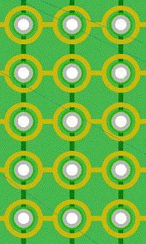
I've had another "interesting" idea for data entry on the cheap: A Matrix of copper traces on a PCB with a grounded test lead "stylus" that allows the SX to "follow" the tracing of the lead against the matrix. The center of each pad in the matrix is plated through to the vertical traces on the other side of the board and each pad is circled by a ring of copper on the top side and these rings are connected horizontally. The vertical and horizontal traces are connected to port pins so that as the test lead is dragged over the top of the board, as it contacts a ring or a pad, the pin attached to that row or column is pulled low.
No need for debounce, you just record the "last x" and "last y" and update them when ever a signal comes in. If neither a row or column update occurs in a certain time (count down timer) then the "pen" is assumed to be "up." Some care must be taken to ensure that the center pad is "hit" as you pass the "pen" from column to column. What I have found is that running a large (.2 or so) curve on the end of a metal ink pen case (with the inside removed) makes it very easy to "click" from hole to hole in the pattern of the digit you want to enter.
A 3 x 5 matrix should be enough for entering text and numbers and a 2x3 works fine for numbers.
The primary feature is low cost combined with easy, fast, data entry. One issue would be converting the pattern after a "pin up" into a letter or digit. I think following the path is a better idea:
 In this
illustration, the starting position has been shown in blue and the areas
that are traced over twice are shown in a darker red. The expected sequence
for a 1 is (2,1),(2,2),(2,3) and for an 8 is
(1,1),(1,2),(2,2),(2,3),(1,3),(1,2),(2,2),(2,1),(1,1). This might seem hard
to match at first, but if you realize that each of the coordinates is really
a single value (e.g. 1 is really 2*3 + 1 = 7 then 2*3 + 2 = 8 then 2 * 3
+ 3 = 9 so the sequence is 7,8,9) then you can use the keyword matcher at:
In this
illustration, the starting position has been shown in blue and the areas
that are traced over twice are shown in a darker red. The expected sequence
for a 1 is (2,1),(2,2),(2,3) and for an 8 is
(1,1),(1,2),(2,2),(2,3),(1,3),(1,2),(2,2),(2,1),(1,1). This might seem hard
to match at first, but if you realize that each of the coordinates is really
a single value (e.g. 1 is really 2*3 + 1 = 7 then 2*3 + 2 = 8 then 2 * 3
+ 3 = 9 so the sequence is 7,8,9) then you can use the keyword matcher at:
http://www.piclist.com/techref/piclist/codegen/keyword_interpreter.htm
to find each sequence. For this figure, you can see the result for 1 thru
0 by
clicking
here.
Here is some code to read and update the last known posiiton. This has not been tested!
	mov	temp, #$F8	;assumes a 3 x 5 matrix; mask the top 5 first.
	mov	w, port	;read the port
	test	w	;check it
	sz		;and if zero do not
	 clr	count	; reset the counter
	dec	count	;count down each time
	add	w,temp	;if any bit was set in the top 5 bits, we will get a carry
			;and the high 5 bits of W contain the column minus 1.
			;(adding all bits = subtracting one)
	sc		;if we found a row contact do not
	 not	temp	; invert the mask. doesn't affect carry, inverts temp to $07
	sc		;if we found a row contact do not
	 and	w, temp ; clear off the bits we added up top
	jz	:none	;won't be if the and was skiped or if any lower bits in W are set

;update the last known position. This may change the top or bottom set of bits in pos
;but will not change both depending on the state of temp (e.g. temp may be $07 or $F8?)
	and	w,temp	;turn off the other bits (high or low depending on what was found)
	or	pos,w	;turn on any bits in pos that are on in W
	not	temp	;swap the mask to the other set of bits
	or	w,temp	;and turn on the other bits (high or low depending...)
	and	pos,w	;turn off any bits in pos that are off in W
Anyway, it's just another crazy idea! <GRIN> But it might combine nicely with an LED matrix.
These neat methods can also be applied to LEDs. Imagine a 4x4 matrix where the four rows go to four I/O lines and the four columns do too. Put 12 LEDs at the non-diagonal junctions with the anodes connected to the columns.
    0   1   2   3
    |   |   |   |
0---+--LED-LED-LED-
    |   |   |   |
1--LED--+--LED-LED-    4 lines, 4(4-1) = 12 LEDs
    |   |   |   |
2--LED-LED--+--LED-
    |   |   |   |
3--LED-LED-LED--+--
    |   |   |   |
You can turn on any LED at will. For example, if you bring line 0 high, line 1 low, and make lines 2 & 3 hi-Z inputs, then the top LED in the first column will light up.
Even though there appear to be multiple current paths, only one path has one LED, and once it lights, the others won't reach their threshold voltage. Pretty cool, huh?
Sadly, I don't see any way to combine this with a keyboard scanning matrix, so you would have to allocate seperate IO lines.z
And now for something completely different. Here is some nice code to generate
a 3-phase sine wave for big time electric motor control. This comes
from:
http://www.piclist.com/techref/member/hb-operamail-885/index.htm
and I converted it for the SX
; PIC 3-Phase generator by Helge Buen - buen@operamail.com

; I borrowed and altered the table lookup and it's driver code. It is Copyright 1995 Eric Smith


; Fixed PWM frequency 3-phase sine generator for electric motors etc.. The output frequency are generated by jumps in the
; sine lookup table. For example the lowest frequency will repeat each value 16 times (4096 values). The highest will do
; 15 and 16 jumps (only 16.5 values - maybe too few, not tested). All others generated by combinations of repeat/jump.

; The code is not tested in practice.

; Electric motors needs the voltage to follow the frequency. Therefore each sine value is multiplied by a factor (gain).
; The frequency (speed) and the gain variables are INDEPENDENT in the code. The simplest and most suitable would be to
; right rotate the gain into the speed variable. At a gain of 255 the controller would output 36 values a revolution at
; full voltage. If one want some voltage boost (motor torque) at particular conditions that is easy to implement too.
; Of course it would be interesting to monitor the speed of the motor and REDUCE voltage to save power on battry apps.

; This code generates 3 values ranging from 2 - 128 and 128-254. 128 is 0 volt and corresponds to the 50% PWM ratio (bridge).
; A separate PWM controller is required as it have to output some thousand pulses a second at 255 resolution
; The PWM controller should have fixed instruction number, master the time and clock the sine generator (handshake).
; It is an good idea to centre the PWM pulses to avoid simultaneously switching (noise)

; No speed ramping (frequency increment) is implemented, it should correspond the mecanical application. Hovever increasing
; the speed variable by one each revolution would be no problem. It is possible to alter the speed/gain at each PWM pulse,
; be aware! The 3 motor voltages should be output simultaneosly at the end.


; 08.09.01: PWM data preparation:

; Convertion of the voltage values into 4 delays and 2 data bytes. The purpose is to do as much processing as possible in
; the generator controller. At the same time not too much data should be created because of the transfer time to the PWM.
; The delays represent time between changes and the data is what to be output. The sum of all delays always is 256. Note:
; they are complements to 256 and 0 must be treated as zero delay. Usual method: before counting them up (incfsz),
; initially subtract 1 from all. Before counting down, add 1 to all. (Use decf/incf instead of movf at data transfer)

; Now, simply load 4 'counter' and 2 'data' registers in the PWM. Count first UP to zero, output data one, count next and so
; on. The third data output is given to be all set. This method introduce small errors, but i believe they are unessential
; to this application. Remember to compensate (at the other end) for the data transfer dead time.

; To implement centered pulses the 4 delays must initially be loaded twice, and second copy count DOWN at the 'mirror part'.
; The data must be inverted (comf). This also requires twice as fast controller. A 20MHz controller is beginning to reach
; the limit here if you want reasonable switching frequency (>3KHz). Another idea i had was to do the first PWM half in the
; generator, and the second in the PWM as the generator carry out processing.

; Note that there is only 3 outputs, but 6 are necessary for 3 phase output bridges. The additinal 3 signals are kind of
; inverted versions, but cross over delay must be insterted. That is a very short period where none of the transistor pairs
; are on, to protect them. I have no idea how long this period should be, but a very long period would decrease the dynamic
; range of the PWM. If someone has any experience about this, please let me know! Also ideas about fast paralell data
; transfers PIC to PIC wanted. The cross over delay and inverted signals could either be made in the PWM controller or in
; the transistor driver stage (depending on delay value). I think the PIC would do it most nice but, again, it's pretty busy.

; Outputs are delay1-4 and data 1-2.

	list p=16c55a

	; Include file, change directory if needed
	org 8
	ds zero
	ds temp	equ	$0009
	ds angle	equ	$000A
	ds gain	equ	$000B
	ds volt1	equ	$000C
	ds volt2	equ	$000D
	ds volt3	equ	$000E
	ds speed	equ	$000F
	ds lsbpos	equ	$0010
	ds delay0	equ	$0011
	ds delay1	equ	$0012
	ds delay2	equ	$0013
	ds delay3	equ	$0014
	ds delay4	equ	$0015
	ds data0	equ	$001A
	ds data1	equ	$001B
	ds data2	equ	$001C


	; Start at the reset vector
	org	$000

	jmp	start

sinetbl:
	add	PC, W
	retw	000h
	retw	003h
	retw	006h
	retw	009h
	retw	00Ch
	retw	010h
	retw	013h
	retw	016h
	retw	019h
	retw	01Ch
	retw	01Fh
	retw	022h
	retw	025h
	retw	028h
	retw	02Bh
	retw	02Eh
	retw	031h
	retw	033h
	retw	036h
	retw	039h
	retw	03Ch
	retw	03Fh
	retw	041h
	retw	044h
	retw	047h
	retw	049h
	retw	04Ch
	retw	04Eh
	retw	051h
	retw	053h
	retw	055h
	retw	058h
	retw	05Ah
	retw	05Ch
	retw	05Eh
	retw	060h
	retw	062h
	retw	064h
	retw	066h
	retw	068h
	retw	06Ah
	retw	06Bh
	retw	06Dh
	retw	06Fh
	retw	070h
	retw	071h
	retw	073h
	retw	074h
	retw	075h
	retw	076h
	retw	078h
	retw	079h
	retw	07Ah
	retw	07Ah
	retw	07Bh
	retw	07Ch
	retw	07Dh
	retw	07Dh
	retw	07Eh
	retw	07Eh
	retw	07Eh
	retw	07Fh
	retw	07Fh
	retw	07Fh
	retw	07Fh


sort	clr	data0		;Subroutine to sort PWM data. (see driver comments)
	mov	W, volt1
	mov	delay0, W	;Presume volt1 is greatest
	setb	data0.0		;And set it's output
	mov	W, volt2
	mov	W, delay0-w	;Test volt2 against volt1
	snb	Z		;Equal?
	setb	data0.1		;Yes, just set that bit too (They share delay)
	snb	C		;Volt2 greater?
	jmp	test3		;No, go testing volt3
	rl	data0		;Yes, change output (Carry known to be zero)
	mov	W, volt2
	mov	delay0, W	;And correct delay
test3	mov	W, volt3
	mov	W, delay0-w	;Test volt3 against the greatest
	snb	Z		;Equal?
	setb	data0.2		;Yes, just set that bit too (They share delay)
	snb	C		;Volt3 greater?
	jmp	diff		;No, go calculate difference
	clr	data0
	setb	data0.2		;Yes, set that output
	mov	W, volt3
	mov	delay0, W	;And correct delay

diff	mov	W, delay0	;Get result
	mov	W, zero-w	;Complement and..
	add	volt1, W	;..calc. DIFFERENCE to next (included voltage(s) are zeroed and excluded in next sort)
	add	volt2, W
	add	volt3, W
	retw	0


start:

	clr	zero
	clr	angle
	clr	lsbpos
	mov	W, #127
	mov	speed, W	; Desired motor frequency. Values above 127 may generate too few sine values?? (<36 a revolution)
	mov	W, #255
	mov	gain, W		; Desired motor voltage. Should follow the frequency (max desired speed -> gain=255)


frame	mov	W, angle
	mov	temp, W		; copy the angle
	snb	temp.6		; is angle in the 2nd or 4th quadrant?
	mov	W, zero-w	; yes, complement it to reduce to 1st or 3rd
	and	W, #07fh	; reduce to 1st quadrant
	call	sinetbl		; get magnitude
	clr	volt1		; empty the output
	clrb	C		; Multiply the gain..
	snb	gain.0
	add	volt1, W
	rr	volt1
	clrb	C
	snb	gain.1
	add	volt1, W
	rr	volt1
	clrb	C
	snb	gain.2
	add	volt1, W
	rr	volt1
	clrb	C
	snb	gain.3
	add	volt1, W
	rr	volt1
	clrb	C
	snb	gain.4
	add	volt1, W
	rr	volt1
	clrb	C
	snb	gain.5
	add	volt1, W
	rr	volt1
	clrb	C
	snb	gain.6
	add	volt1, W
	rr	volt1
	clrb	C
	snb	gain.7
	add	volt1, W
	mov	W, >>volt1
	snb	temp.7		; was angle in 3rd or 4th quadrant?
	mov	W, zero-w	; yes, complement it
	xor	W, #128		; align to center
	mov	volt1, W

	mov	W, #85		; 120 degrees offset for phase 2
	add	W, angle
	mov	temp, W
	snb	temp.6		; is angle in the 2nd or 4th quadrant?
	mov	W, zero-w	; yes, complement it to reduce to 1st or 3rd
	and	W, #07fh	; reduce to 1st quadrant
	call	sinetbl		; get magnitude
	clr	volt2		; empty the output
	clrb	C		; Multiply the gain..
	snb	gain.0
	add	volt2, W
	rr	volt2
	clrb	C
	snb	gain.1
	add	volt2, W
	rr	volt2
	clrb	C
	snb	gain.2
	add	volt2, W
	rr	volt2
	clrb	C
	snb	gain.3
	add	volt2, W
	rr	volt2
	clrb	C
	snb	gain.4
	add	volt2, W
	rr	volt2
	clrb	C
	snb	gain.5
	add	volt2, W
	rr	volt2
	clrb	C
	snb	gain.6
	add	volt2, W
	rr	volt2
	clrb	C
	snb	gain.7
	add	volt2, W
	mov	W, >>volt2
	snb	temp.7		; was angle in 3rd or 4th quadrant?
	mov	W, zero-w	; yes, complement it
	xor	W, #128		; align to center
	mov	volt2, W

	mov	W, #170		; 240 degree offset for phase 3
	add	W, angle
	mov	temp, W
	snb	temp.6		; is angle in the 2nd or 4th quadrant?
	mov	W, zero-w	; yes, complement it to reduce to 1st or 3rd
	and	W, #07fh	; reduce to 1st quadrant
	call	sinetbl		; get magnitude
	clr	volt3		; empty the output
	clrb	C		; Multiply the gain..
	snb	gain.0
	add	volt3, W
	rr	volt3
	clrb	C
	snb	gain.1
	add	volt3, W
	rr	volt3
	clrb	C
	snb	gain.2
	add	volt3, W
	rr	volt3
	clrb	C
	snb	gain.3
	add	volt3, W
	rr	volt3
	clrb	C
	snb	gain.4
	add	volt3, W
	rr	volt3
	clrb	C
	snb	gain.5
	add	volt3, W
	rr	volt3
	clrb	C
	snb	gain.6
	add	volt3, W
	rr	volt3
	clrb	C
	snb	gain.7
	add	volt3, W
	mov	W, >>volt3
	snb	temp.7		; was angle in 3rd or 4th quadrant?
	mov	W, zero-w	; yes, complement it
	xor	W, #128		; align to center
	mov	volt3, W


	call	sort		;Format voltages to PWM delays and data to disengage PWM controller.
	mov	W, delay0
	mov	delay1, W	;Store first delay
	mov	W, data0
	mov	data1, W	;Store first data
	call	sort
	mov	W, delay0
	mov	delay2, W	;Store second delay
	mov	W, data0
	or	W, data1	;Include first and..
	mov	data2, W	;..store second data (Third data is given to be simply all switched on)
	clr	W		;Find the third delay by checking data. If all set -> zero. (Shared with another)
	sb	data2.0
	mov	W, volt1
	sb	data2.1
	mov	W, volt2
	sb	data2.2
	mov	W, volt3
	mov	delay3, W
	add	W, delay1	;Calculate the fourth delay (sum of previous and this delay -> 256)
	add	W, delay2
	mov	W, zero-w	;Complement
	mov	delay4, W

	mov	W, speed	; Lookup table pattern generator..
	add	lsbpos, W
	snb	DC
	inc	angle
	mov	W, <>speed
	and	W, #15
	add	angle, W

	jmp	frame

	END
| file: /Techref/new/letter/news0303.htm, 29KB, , updated: 2016/7/6 10:45, local time: 2025/10/14 21:49,
216.73.216.155,10-3-165-151:LOG IN
|
| ©2025 These pages are served without commercial sponsorship. (No popup ads, etc...).Bandwidth abuse increases hosting cost forcing sponsorship or shutdown. This server aggressively defends against automated copying for any reason including offline viewing, duplication, etc... Please respect this requirement and DO NOT RIP THIS SITE. Questions? <A HREF="http://www.ecomorder.com/techref/new/letter/news0303.htm"> Massmind news letter, March 2003</A> |
| Did you find what you needed? |
Welcome to ecomorder.com! |
Welcome to www.ecomorder.com! |
.