Roman Black [fastvid at EZY.NET.AU] says:
Firstly I made a simple header. This is a long-legged 18pin socket to go into the PSP, with four wires soldered to it.Here are the wires:
* Gnd (Vss) -----       ground wire
* MCLR      --R--       470 ohm series resistor
* RB7       --R--       470 ohm series resistor
* RB6       --R--       470 ohm series resistor
These connect to the same PIC pins on the app, in my case I designed the app board with the 470 ohm resistors on the board and a nice plug for the ICSP.
Important, I used no capacitors on the app on the MCLR pin. I just used a 68,000 ohm resistor to hold the MCLR high to 5v when in normal operating mode. This is very simple, and has low parts cost.
To program the app, I simply connected power to it (via a on/off switch) from my regular power source not from the PSP. The PSP does NOT power the amp or the pic when programming in this circuit. I connected the ground from the PSP to the ground of the app's power supply of course.
One the app was powered, the PSP holds the app in reset mode as it holds the MCLR pin at 0v. Then I used MPLAB as normal to program or read the 16F84 in the app. This works as normal, like when programming a 16F84 in the socket of the PSP.
When programming is complete I can just switch the app power off, unplug the programming plug, and switch the app power back on to run the app as normal. Quick and easy!
Just a couple of notes, app's that use a "reset" chip on the MCLR line may need to make some changes to ensure that the PSP can draw the MCLR line to 13v very quickly to ensure good programming. Also my app used the RB7 and RB6 as inputs, so also using these for the ICSP gave no problems. I tested adding 10k resistors to both these pins to 0v, and tested again with the 10k resistors to 5v. Both cases the ICSP still worked fine. I would guess that means that you don't need to "buffer" these pins but simply use a 10k resistor to your circuit and you can still use them as inputs.
I have programmed the thing with a number of 16F84 chips, and programmed it a couple of hundred times with NO program or read failures (unless I forget to switch the app on before programming!).
I know this is a long letter and I apologise to the PIC experts who probably know all of this, just seen a few newbies ask about ICSP lately and not everyone has the budget or desire to spend big bucks on ICSP. YES, you CAN do ICSP with a picstart plus.
Vlado Kecman [vlado.kecman at DATAKEY.COM] says:
Thanks to Roman, David and other people to introduce me with this matter.My experience using the Picstart Plus for ICSP applied on the PIC16F873 is following:
The five standard ICSP signals (Vdd, GND, MCLR, RB6, and RB7) are connected from the board to the programmer. Power Vdd from programmer is separated from Vcc on the board with a Schottky diode. MCLR has pull-up 10K via a diode (1N4148) and Cap 0.01uF to the GND.
- Picstart Plus (Firmware V.2.01.00)
Programmer always uses Vihh (13V) for programming and does not control pin RB3. I thought LVP enable implies low voltage programming mode but it only determines LVP config bit. For this mode in the PIC16F87X Spec is noted: The high voltage programming mode is always available, regardless of the state of the LVP bit, by applying Vihh to the MCLR pin.
- LVP Enable programming (LVP config. bit is set)
RB6 and RB7 are set as output. Programming works w/ or w/o pull-up or pull-down resistors. Programmer does not care for RB3, but it can not be used in application. I set it as output and pull down with 10K. If I leave it to float, despite it is set as output, PIC will be very sensitive to any disturbances. Touching with finger pushes PIC somewhere (program modes?) after it passes reset and recovers to work. In this case RB6, RB7 are set as output with 33K pull-ups? WDT is disabled.
- LVP Disable (LVP bit is cleared)
I have no any problem with this mode. RB3 is used by my application. RB6 and RB7 could be used but I don t need them. They are set as output with pull-up 33K, and 1K toward input.
- Conclusion
- High voltage programming mode is very convenient. LVP bit can be cleared or set how much time you want but once it is cleared only high voltage programming mode is available. Changing LVP bit actually has only effect on the application possibility to use or not use RB3 pin.
- If you do not really need LVP mode, disable it. You will get one pin more and less worry about unwilling program/verify mode.
- LVP disable mode does not release you from possibility to go into unwilling program mode. Spikes from solenoid in my application sometime push PIC into undefined mode because of high sensitivity of the MCLR pin. I can not apply a 5V transzorb (Vihh=13V), but a Cap. 0.01uF can help by now. Good protection of the MCLR pin has also to meet driving capability of the programmer.
Jinx says:
...logically it has to work if switching is used, because all you have then is the isolated PIC and the programmer. It's not that much of a pain to set up, and saves a hell of a lot of plugging and unplugging PICs. Other programmers have drive designed to power user circuits, The PS+ should not be stressed like that without careful and considered thought (I wouldn't risk mine anyway under any circumstances)
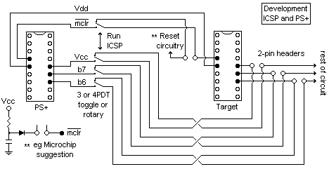
"PS+" is an 18-pin IC socket that has wires soldered to where the IC pins would normally go. This socket is inserted into the PS+ in place of the PIC. For other PICs, identify the active pins and use a smaller / larger socket as appropriate. Alternativly, a small PCB could be made that has the switch mounted ont he back of the IC socket.
"target" is the PIC device on the user circuit board. If circuit Vcc is the same as the PS+ (nominally 5.0V) then either can be used to power the PIC during programming
During programming the switch is set ot the "ISCP" position, which isolates the PIC from the circuit, and the hex is downloaded to the PIC. When this is complete, the switch is moved to the "run" position and the PIC will be isolated from the PS+
When ICSP has been finished with, the ICSP connection can be removed and the 2-PIN headers shorted out. The 3 or 4 headers can be placed so that 3 or 4 jumpers glued together in a block makes this easier.
Questions:
See also:
Comments:
| file: /Techref/microchip/picstartplusicsp.htm, 8KB, , updated: 2007/5/11 11:09, local time: 2025/10/6 13:59,
216.73.216.4,10-3-204-28:LOG IN
|
| ©2025 These pages are served without commercial sponsorship. (No popup ads, etc...).Bandwidth abuse increases hosting cost forcing sponsorship or shutdown. This server aggressively defends against automated copying for any reason including offline viewing, duplication, etc... Please respect this requirement and DO NOT RIP THIS SITE. Questions? <A HREF="http://www.ecomorder.com/techref/microchip/picstartplusicsp.htm"> PIC Microcontroller PIC Start Plus Programmer Using the Picstart Plus for ICSP</A> |
| Did you find what you needed? |
Welcome to ecomorder.com! |
Welcome to www.ecomorder.com! |
.