Capable motion control from a $2 PIC and an $8 PCB? Yep! The higher end PICs that can be installed on the BOB Panel board actually have enough power to provide ultra low cost motion control: Accepting G-Code commands from a PC (via the RLC3 USB adapter) and producing step and direction for several axis CNC Mill, etc... control. Of course, that depends on a PIC wizard like VegiPete writing hand optimized assembly code to run the critical parts.
All the standard G-CODE commands are supported, 4 axis, XYZ plus A (or E), rapids, feedrates, etc... With a ESP-8266 Serial to Web interface, the browser interface can add features like remote interface, preview, status display, easy configuration, etc..
Connect to the controller at 38,400 baud, N81, Xon/Xoff handshaking. A serial to USB converter like the RLC3 provides easy connection to modern computers or a low cost ESP-8266 unit can provide a Web interface. After power on or reset (S1 option during Assembly) you should see:
;GPICode v0.83
Followed by the current configuration (see below) and then the homing sequence if set to automatically home on startup or ;Waiting for Home command.
The unit is now ready to recieve commands via G-CODE. See
http://www.linuxcnc.org/docs/2.4/html/gcode_overview.html
for a more detailed overview of G-CODE.
A block is one line of text consisting of one or more "words" where each word consists of a letter and a number. White space is ignored. Lower case is converted to upper. A line of text ends with a CR and/or a LF.
A number can be positive or negative and may contain a decimal. A number begins with optional '+' or '-' and ends with any non digit. Extra decimal points are ignored. 12.34.56 = 12.3456 Extra +/- signs restart the number. +12.3-4.5 = -4.5 (The number of decimal digits is specified in the config and excess digits are ignored.
To see the current configuration values, send the command
(CF
The current configuration is displayed and appears as follows:
;Config:
;Steps/inch X:+10000 Y:-10000 Z:+10000 A:+10000
;Fmax(F):60000 Accel(D):00030 SigFigs(B):4 BlockDel(C):ON
;Homing Config(E):ON
;Back speed: 100
;01 Y 050 040 010
;81 Y 050 040 020
;00 - 050 040 200
;80 - 025 040 010
To change configuration, send (CF followed by the letters and values to set the configuration parameters. All configuration values are integers. Decimal places are ignored. Case sensitive (use upper case letter). A web page to ease configuration settings is available bobmotion-setup.html
A,X,Y and Z are the steps per inch for the corresponding axes. Negative values reverse the direction of the axis.
F is the maximum speed. (All axes use the same value.) Inches (or mm) per minute
D is the acceleration value for all axes. Same units as F. Start with 30 and adjust up until there are problems, then back off for stable operation.
B is number of recognized decimal places. Extra decimal digits are ignored with no rounding. For example, if N=3, 3.141592 is treated as 3.141.
C is block delete. 0 turns it off, any other value turns it on. When on, any block starting with "/" is ignored. When off, any block starting with "/" is processed as if the "/" were not present. (Note: untested with "(CFG" blocks.)
E - power-up home if not zero
G - homing back-off speed
H - step 1 axis & direction bit pattern
I - step 1 speed
J - step 1 timeout
K - step 1 back-off distance
L - \
M - \ step 2
N - /
O - /
P - \
Q - \ step 3
R - /
S - /
T - \
U - \ step 4
V - /
W - /
For example:
(CF X 2000
(CF Y 2000
(CF Z 2000
(CF A 2000
(CF D 1000
(CF F 500
(CF B 3
(CF C 1
(CF E 1
(CF G 2
(CF H 2
(CF I 42
(CF J 40
(CF K 1
(CF L 1
(CF M 42
(CF N 40
(CF O 1
(CF P 16
(CF Q 42
(CF R 40
(CF S 1
(CF T 32
(CF U 42
(CF V 40
(CF W 1
(MSConfig updated.
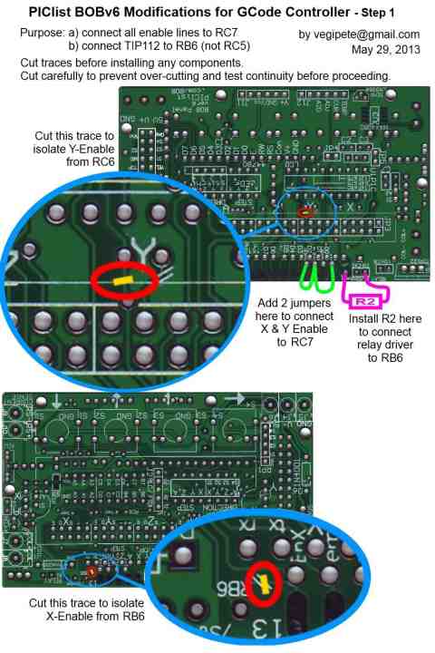
In order to accomodate the reduced number of pins on the PIC vs the Parallel Port on a PC, if your drivers depend on an enable signal from the controller, we have to modify the board to consolidate all the drive enable lines into one signal. Since Z and A are already together, that means cutting the traces that connect X and Y enables and then jumpering them to Z/A. See the info graphic here for those modifications, and the correct installation of R2 (required if you want spindle relay control). If your drivers don't need an enable signal, simply don't connect it at the driver.
After the board modifications, install
The power and ground pins (pins 1 and 3) are swapped on J2, the serial adapter cable. If you are using an FTDI cable, be sure to swap the pins around in the cable connector before plugging it in.
See also:
Setup configuration calculator
| file: /Techref/microchip/bobmotion-gcode-vp.htm, 14KB, , updated: 2017/2/18 17:56, local time: 2025/10/11 01:16,
216.73.216.155,10-3-165-151:LOG IN
|
| ©2025 These pages are served without commercial sponsorship. (No popup ads, etc...).Bandwidth abuse increases hosting cost forcing sponsorship or shutdown. This server aggressively defends against automated copying for any reason including offline viewing, duplication, etc... Please respect this requirement and DO NOT RIP THIS SITE. Questions? <A HREF="http://www.ecomorder.com/Techref/microchip/bobmotion-gcode-vp.htm"> BOB Motion Control gcode to multi-axis step/direction motor driver</A> |
| Did you find what you needed? |
Welcome to ecomorder.com! |
Welcome to www.ecomorder.com! |
.